I’ve been playing with a couple of Arduinos for the last week, and doing some physical computing, interfacing with real devices from the microcontroller. It’s been interesting doing some low level electronics again, and it was a great feeling about half an hour ago to have the model railway running under computer control – using the laptop to send commands over the USB port to the Arduino, which then does PWM to control the speed of the train.
There were a few hiccups along the way – not least of which the Arduino crashed repeatedly when the train started moving – it appears that the power pack I was using didn’t like having its load being PWMed, causing voltage problems. I resorted to running the Arduino off the USB supply, disconnecting the common 12V power input to the board, and just using that external power pack to provide power for the direction change relay and output to the loco. Make sure that you keep the ground connected though, as the Darlington TIP120s need that to be common in order to work.
The eventual use for this project is to automate the model layout in the Corris Railway Museum, and allow visitors to put coins in a slot and the train will then run for a number of returns depending on the coin put in. More coins – the train runs a little quicker. The software allows for reed switches at either end of the line for reversing, as well as reed switches for stations.
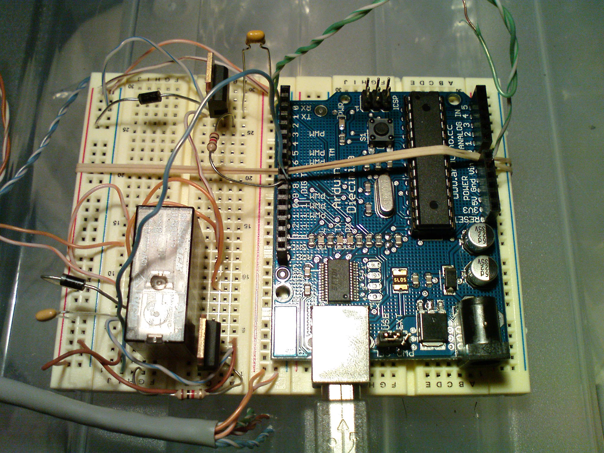
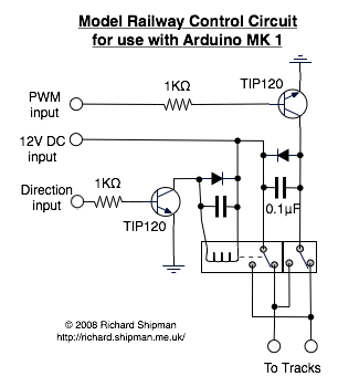
The hardware driver circuit is shown here in the schematic below (I know it’s pretty rough, but it’s as good as I can do at short notice), and photo of the really dodgy looking breadboard prototype.
The diodes are 1N4004s and the caps are 0.1μF to protect against reverse current from the inductive loads.