Facit 4070 paper tape punching with Arduino mega

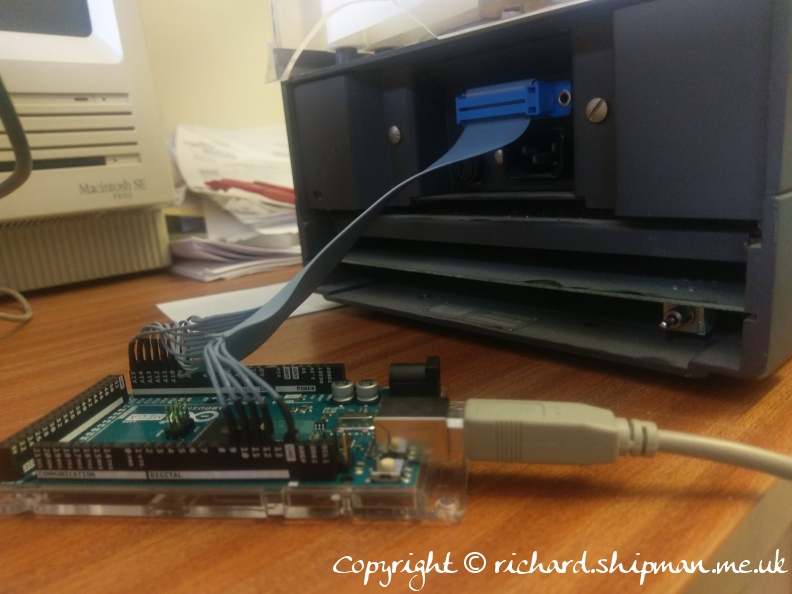
A couple of months ago, I had a request from a friend to produce a paper tape as an RSVP to a wedding invitation that he’d received on floppy disk. I dug out my old Facit 4070 in my collection and set to seeing if I could interface it with something modern. This blog post chronicles the results.

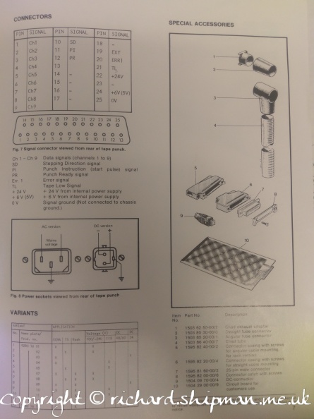
Connection from Facit 4070 to Arduino Mega for code:

Facit 4070 D -> Arduino Mega Pin
1 -> A8
2 -> A9
3 -> A10
4 -> A11
5 -> A12
6 -> A13
7 -> A14
8 -> A15
9 -> D9
10 -> D10
11 -> D11
12 -> D12
25 -> GND

I didn’t actually use pin 12 (Punch Ready) in the end, as it was proving unreliable, so I just used timings – a quick and dirty solution was all that was needed, and eventually it proved robust enough with delays in sending the data.

The code was written to take commands from a menu system to set up the arduino and then punch data.  The menu is as below:

Facit 4070 printer arduino interface
====================================
? - show this information
a - punch message in ascii
b - punch message in EIA code
c - clear message
d - display message
e - punch message in ebcdic (no parity)
f - advance tape 10 spaces and punch feed holes
h - punch message human readable
m - enter message
o - toggle odd or even parity
p - turn on/off parity
s - advance tape 10 spaces
v - show version information

To use it, you send an ‘m’ followed by your message.  You then can select if you want parity or not, and odd or even parity if you’re using ascii.  Following that, you can send an ‘a’, ‘b’, ‘e’ or ‘h’ depending on what character encoding you want to use.


Photo gallery of Facit 4070 project

Github repository of Arduino code to drive Facit 4070

Video on Facebook of the punch working

Arduino Pong Clock

I am currently enjoying building interesting electronic clocks. I’ve built a couple of nixie clocks from kits, but I came across an Arduino project on make magazine blog. It linked to Nick’s LED Pong clock so I ordered the bits and built it in a couple of hours on Sunday afternoon. I bought a different real time clock module to the one that Nick used, mine came from Blue Smoke Labs and is a very neat little module.

So when I got it up and running I decided to put my own twist on it and started playing with the code a bit. First I added lowercase letters to the font and altered the character drawing routine to accommodate them. Next I added some space invader characters to the font and played around with adding a couple of animations to scroll them across the screen. Thirdly I thought that I’d try to replicate some of the functionality that I have on the nixie clocks and add a nighttime mode that allows the clock to dim between certain hours.

These changes took me a few hours, and tidying up the bits of code things stopped working – especially the button press routines, so I fiddled with the code for a while and before I knew it it was 3am, and I decided that I wasn’t going to fix it so went to bed.

Tonight I came in and methodically worked through my additions and within half an hour I had worked out what the problem was which had been staring me in the face for two hours the night before and had fixed it. Just goes to show what a night’s sleep can do.

Anyhow, a little video of it working showing the lowercase and space invaders follows, still more work to do on the invaders mode and I want to add a scrolling text mode and add some way of setting preferences and storing them in eeprom…lots of ideas.

Arduino I2C Wire library

I’ve spent most of the evening trying to get I2C working between the Arduino and a couple of I2C devices (a LCD output and a relay board) from Robot Electronics. I finally had to look at the source code for the Wire library that implements the TwoWire serial protocol for the Arduino, and found that the library correctly bit shifts the address one bit towards the MSB, but that means that you have to do the reverse bit shift to quote the address on the bus when making the library calls. It all has to do with the fact that it’s a 7 bit addressing system.

I did finally manage to get it to work by dividing all the addreses by two, so that’ll make it easier when I actually get the 6-7.2V supply working for the servo board for controlling the turnouts on the layout.

Bedtime now.

Arduino model railway control

I’ve been playing with a couple of Arduinos for the last week, and doing some physical computing, interfacing with real devices from the microcontroller. It’s been interesting doing some low level electronics again, and it was a great feeling about half an hour ago to have the model railway running under computer control – using the laptop to send commands over the USB port to the Arduino, which then does PWM to control the speed of the train.

There were a few hiccups along the way – not least of which the Arduino crashed repeatedly when the train started moving – it appears that the power pack I was using didn’t like having its load being PWMed, causing voltage problems. I resorted to running the Arduino off the USB supply, disconnecting the common 12V power input to the board, and just using that external power pack to provide power for the direction change relay and output to the loco. Make sure that you keep the ground connected though, as the Darlington TIP120s need that to be common in order to work.

The eventual use for this project is to automate the model layout in the Corris Railway Museum, and allow visitors to put coins in a slot and the train will then run for a number of returns depending on the coin put in. More coins – the train runs a little quicker. The software allows for reed switches at either end of the line for reversing, as well as reed switches for stations.

The hardware driver circuit is shown here in the schematic below (I know it’s pretty rough, but it’s as good as I can do at short notice), and photo of the really dodgy looking breadboard prototype.

The diodes are 1N4004s and the caps are 0.1μF to protect against reverse current from the inductive loads.

MRCC1Breadboard MRCC1